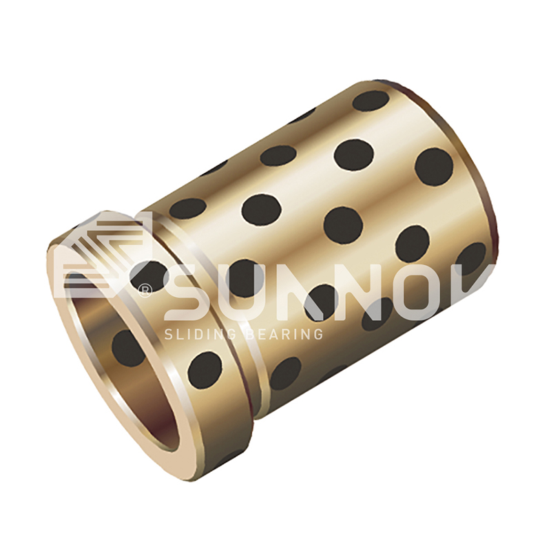
Hjem / Produkt / JDB solid-sprudlende lager / JGBF Brass Oilless Ejector Flanged Guide Bearings Bushings
engros JGBF Brass Oilless Ejector Flanged Guide Bearings Bushings

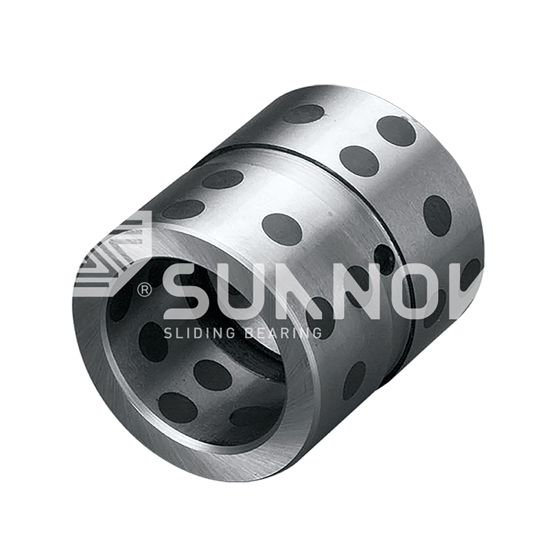
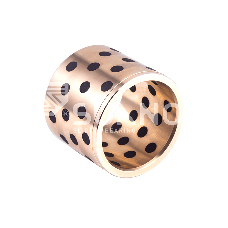
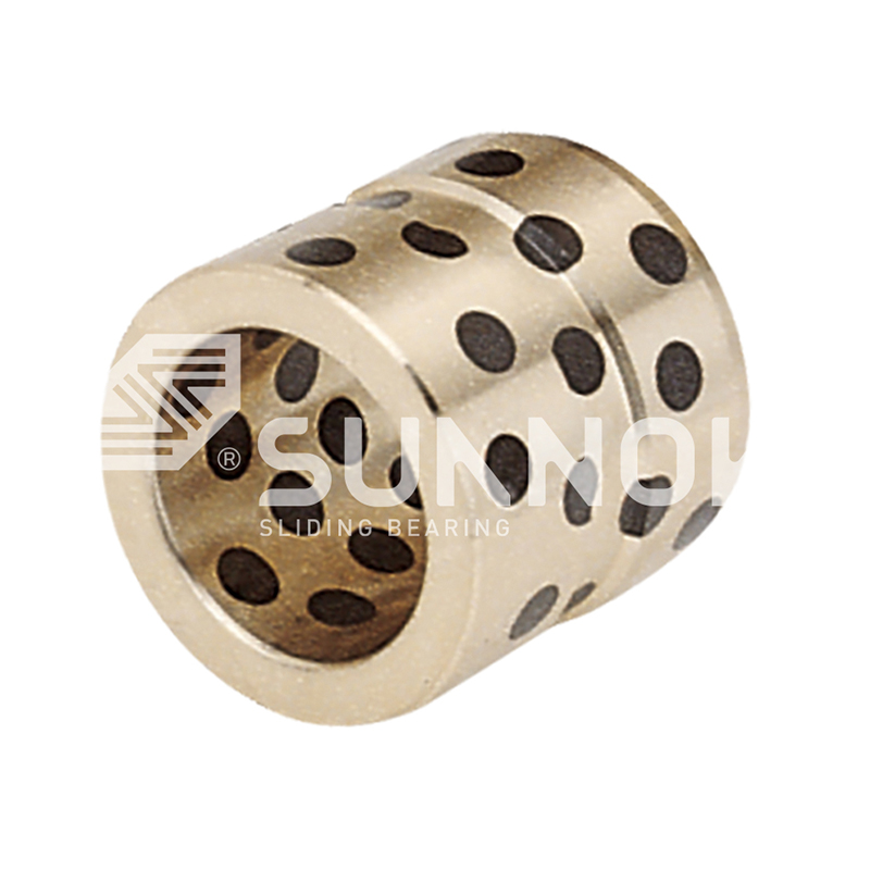
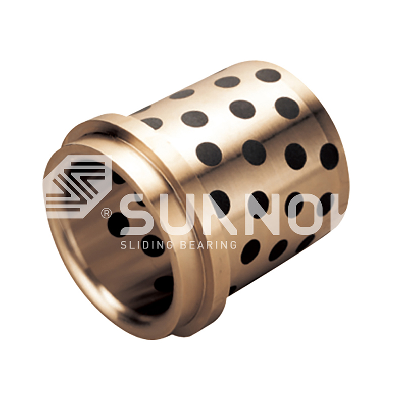
JGBF Brass Oilless Ejector Flanged Guide Bearings Bushings

Produktbeskrivelse:

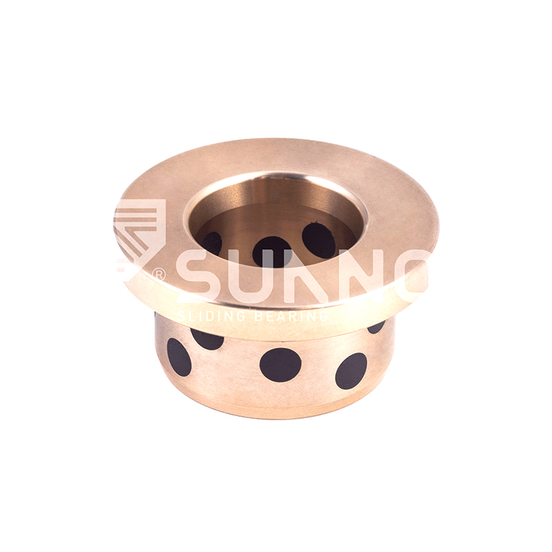
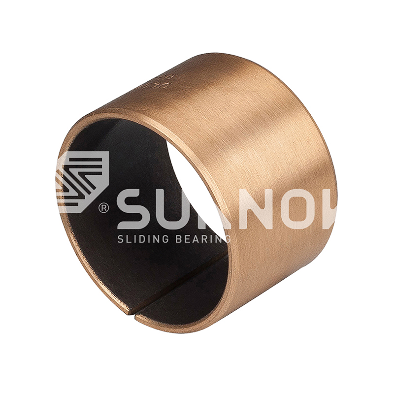
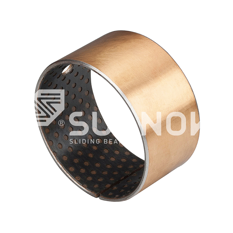
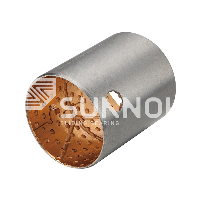
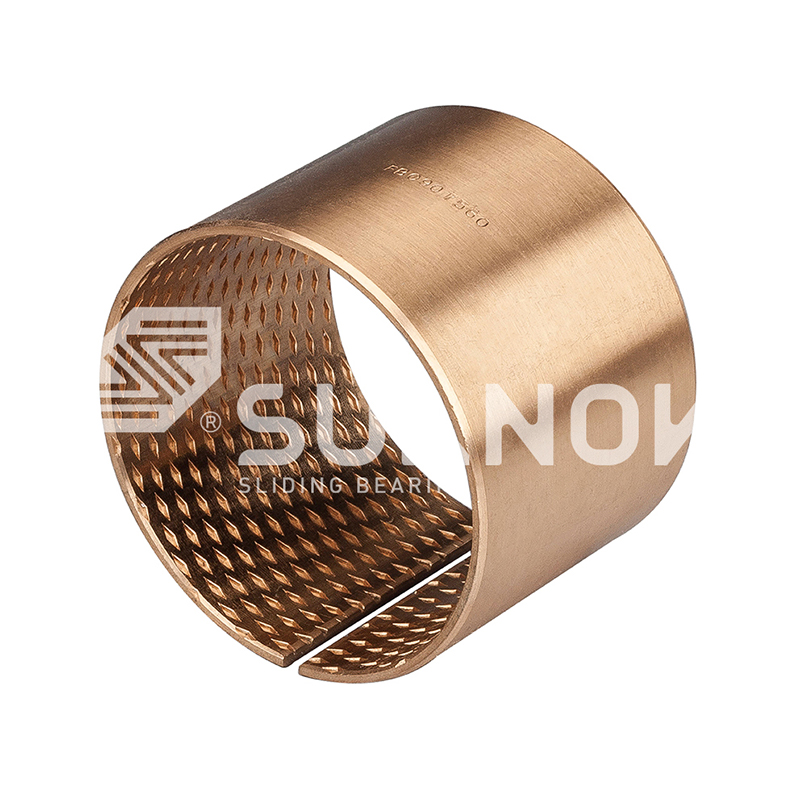
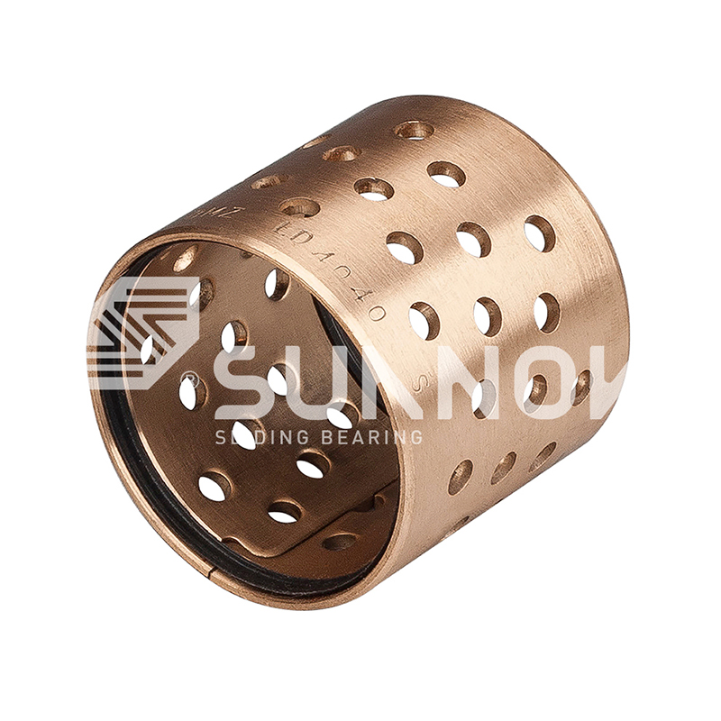
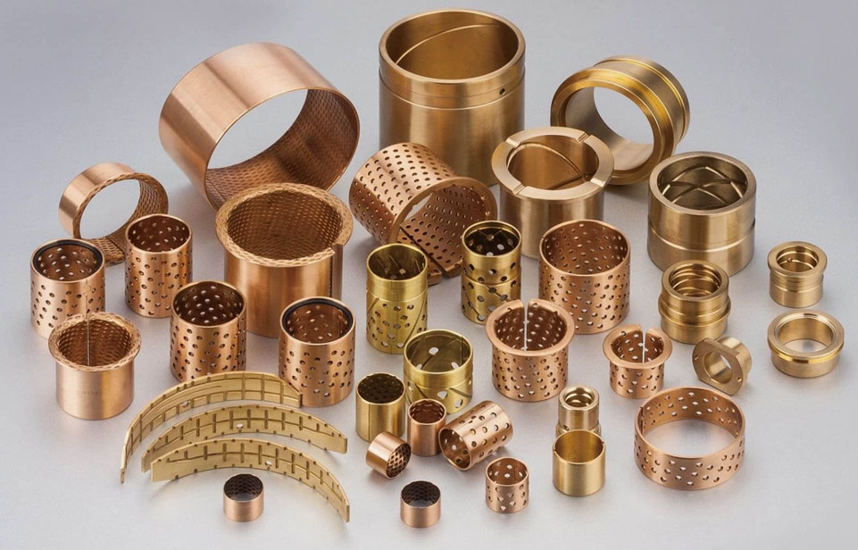
JGBF Brass Oilless Ejector Flanged Guide Bearings Bushings Brass is used as the base material and graphite solid lubricant is embedded in it, which has self-lubricating properties. The bearings have a low friction coefficient (0.05-0.12) and can operate stably under high load and high temperature environments without external lubrication. They have strong wear resistance and long service life. JGBF bearings are corrosion-resistant and suitable for a variety of harsh working conditions. Applications include machinery manufacturing, automobiles, construction, port machinery, agriculture, medical treatment and wind energy, and are widely used in equipment that requires high precision, high load capacity and maintenance-free operation. There are a variety of standard sizes to adapt to a variety of mechanical equipment.


Produktbeskrivelse

Standard No. d L d  G6 D  m6 D1 T L1
JGBF-12×19 12  19  12  +0.016
+0.006
18  +0.018
+0.007
25  19 
JGBF-12×24 24
29
24 
JGBF-12×29 29 
JGBF-12×34 34  34 
JGBF-16×19 16  19  16  25  +0.025
+0.009
30  19 
JGBF-16×24 24  24 
JGBF-16×29 29  29 
JGBF-16×34 34  30 
JGBF-16×39 39
49
30 
JGBF-16×49 30 
JGBF-20×24 20  24  20  +0.020
+0.007
30  35  24 
JGBF-20×29 29  29 
JGBF-20×34 34  34 
JGBF-20×39 39  39 
JGBF-20×49 49 40 
JGBF-20×59 59 40 
JGBF-25×24 25  24 25  35  +0.025
+0.009
40  24 
JGBF-25×29 29 29 
JGBF-25X34 34 34 
JGBF-25X39 39  39 
JGBF-25×49 49  49 
JGBF-25×59 59 50 
JGBF-25×69 69 50 
JGBF-30×29 30  29 30  42 47  10  29 
JGBF-30×34 34 34 
JGBF-30×39 39  39 
JGBF-30×49 49  49 
JGBF-30×59 59  59 
JGBF-30×69 69  60 
JGBF-30×79 79  60 
JGBF-35×39 35  39  35


+0.025
+0.009
48 +0.025
+0.009
54  10 39 
JGBF-35×49 49  49 
JGBF-35×59 59  59 
JGBF-35×69 69  69 
JGBF-35×79 79  70 
JGBF-35×89 89  70 
JGBF-35×99 99  70 
JGBF-40×39 40 39  40 55 +0.030
+0.011
61 39 
JGBF-40×49 49  49 
JGBF-40×59 59  59 
JGBF-40×69 69  69 
JGBF-40×79 79  79 
JGBF-40×89 89  80 
JGBF-40×99 99  80 
JGBF-40×109 109  80 
JGBF-50×49 50 49  50 70 76 12 49 
JGBF-50×59 59  59 
JGBF-50×69 69  69 
JGBF-50×79 79  79 
JGBF-50×89 89  89 
JGBF-50×99 99  90 
JGBF-50×109 109  90 
JGBF-50×119 119  90 
JGBF-60×99 60 99  60  +0.029
+0.010
80  86  15  99 
JGBF-60×109 109  109 
JGBF-60×119 119 110 
JGBF-60×129 129  110 
JGBF-60×149 149  110 

Produktintroduksjon

Flanged Ejector Guide Series

JGBF Brass Oilless Ejector Flanged Guide Bearings Bushings

300
°C
Operating Temperature
Flanged
Configuration
Integral Retention
0.18
μ
Friction at 250°C
Flanged Guide Architecture

The JGBF series combines high temperature brass substrate with an integral flange designed specifically for ejector guide applications. The flange provides positive axial location within the mold or die platen, eliminating the need for separate retaining rings or shoulder bolts. This configuration simplifies installation and ensures consistent guide positioning during thermal cycling. Graphite lubricant inserts are distributed across both the cylindrical guide bore and the flange thrust face, providing lubrication for both radial guidance and axial seating contact. The flanged design also facilitates easier removal during maintenance through access from the flange side.

Flange Diameter 1.5x OD standard
Flange Thickness 2.5mm - 5.0mm
Guide Tolerance ISO H8 at 20°C
F
Flange Retention Integral flange eliminates separate hardware, reduces assembly steps
T
Thermal Stability Special brass alloy maintains dimensional accuracy to 300°C
G
Dual Surface Lubrication Graphite on bore and flange face for combined motion lubrication
E
Ejector Pin Guidance Designed specifically for ejector pin stroke and load requirements

Flanged Design Specifications

Flange Face Flatness 0.015mm per 50mm diameter Perpendicular to bore axis
Flange OD Tolerance ISO h11 Standard clearance fit
Flange Corner Radius R1.0mm maximum Prevents stress concentration
Flange Graphite Pattern Radial insert arrangement 8 inserts on flange face

Flanged Guide Applications

  • Injection molding ejector plates with guided pins
  • Die casting ejector systems requiring axial retention
  • Hot stamping tool ejector mechanisms
  • Thermoforming mold ejector guides
  • Compression molding press ejectors
  • Automated transfer die ejector systems

Flange Integration Benefits

  • Self-aligning flange face with counterbore seat
  • Eliminates separate thrust washer components
  • Reduces assembly time by 40% compared to non-flanged
  • Provides visual confirmation of full seating during installation
  • Allows removal using pry tool without damaging housing

Flanged Configuration Comparison

Feature JGBF Flanged Standard Sleeve With Retaining Ring
Axial Retention Method Integral flange Interference fit only Separate ring
Assembly Components 1 1 2
Disassembly Access Flange side Press out from rear Ring removal required
Axial Load Capacity 45 N/mm² 25 N/mm² 35 N/mm²
Thermal Expansion Matching Optimized for steel Standard Ring dependent

Flanged Guide Size Matrix

Guide ID mm OD mm Flange OD mm Length L mm Flange Thick mm Max Pin Speed m/s
6 10 16 12, 16, 20 2.0 0.6
8 12 20 16, 20, 25 2.5 0.6
10 16 26 20, 25, 30 2.5 0.55
12 18 30 25, 30, 40 3.0 0.5
16 24 38 30, 40, 50 3.0 0.45
20 30 48 40, 50, 60 3.5 0.4
25 36 56 50, 60, 80 4.0 0.35
32 44 68 60, 80, 100 4.0 0.35
40 54 82 80, 100, 120 4.5 0.3
50 66 100 100, 120, 150 5.0 0.3
Flange thickness and diameter can be customized for specific mold platen counterbore dimensions.
Installation Sequence
1 Clean counterbore shoulder and bore. Verify depth matches flange thickness.
2 Chamfer counterbore entry at 1.5mm x 15 degrees to prevent flange edge damage.
3 Apply thin lubricant to housing bore only. Do not apply to guide bore.
4 Press using flat tool contacting flange face uniformly. Press until flange seats.
5 Verify flange flushness with housing surface. Tolerance ±0.05mm.
Frequently Asked Questions
Can the flange face handle thrust loads Yes. Flange face supports axial loads up to 45 N/mm². Graphite inserts on flange provide lubrication during axial contact.
What is the recommended counterbore depth Counterbore depth should equal flange thickness plus 0.05mm clearance for thermal expansion at operating temperature.
How to remove a JGBF bearing Use a pry tool between flange edge and housing. Do not pry against the guide bore or graphite inserts.
Flange eccentricity tolerance Flange OD concentricity to guide ID maintained within 0.05mm TIR for standard production.
Flange Surface Finish Ra 0.8 µm
Bore Surface Finish Ra 0.4 µm
Material Grade CuSn8 High Temp
Graphite Coverage 22% bore / 18% flange
Zhejiang Shuangnuo Bearing Technology Co., Ltd.
Zhejiang Shuangnuo Bearing Technology Co., Ltd. ja Kina JGBF Brass Oilless Ejector Flanged Guide Bearings Bushings leverandør og engros JGBF Brass Oilless Ejector Flanged Guide Bearings Bushings bedrift, Vi er en profesjonell produsent av ulike selvsmørende kobberlegeringsprodukter ved bruk av prosesser som sentrifugalstøping, kontinuerlig støping og metallstøping. Hovedproduktene inkluderer messing, aluminiumsbronse, tinnbronse, etc. produsert i henhold til nasjonale standardkarakterer. På dette grunnlaget bearbeider og produserer vi ulike solide innlagte selvsmørende lagerprodukter. Vi produserer også bimetallprodukter og mange andre typer produkter ved hjelp av sintringsteknologi. I løpet av de nesten ti årene siden etableringen har selskapet fokusert på forskning og utvikling og produksjon av ulike nye selvsmørende lagre.

Under produktproduksjonsprosessen insisterer selskapet alltid på uavhengig støping og produksjon av råvarer for å sikre produktkvalitet fra kilden; støpeprosessen overvåkes gjennomgående, og de ferdige produktene testes tre ganger med spektrometer før, i og etter ovnen for å bekrefte materialsammensetningen til produktet. Selskapet overlater regelmessig nasjonale testinstitusjoner til å teste materialsammensetningen og de mekaniske egenskapene til produktene sine, og kan gi autoritative testrapporter til kunder som trenger det. Selskapet implementerer integrert produksjon fra materiale til ferdig produktbehandling, og har mer enn 80 hovedutstyr som avanserte CNC-maskiner, CNC-dreiebenker og maskineringssentre. Sterk produksjonskapasitet sikrer at materialproduksjon kan organiseres for kundene så raskt som mulig, noe som forkorter produksjonssyklusen.
  • 0+
    Etablering

    Shuangnuo ble grunnlagt i 2014 og har 10 års bransjeerfaring.

  • 0+
    Avansert utstyr

    Sterk produksjonskapasitet sikrer at vi kan organisere materialproduksjon for kundene så raskt som mulig og forkorte produksjonssyklusen.

  • 0+
    Kundetilfredshet

    Vi har mer enn 5000 samarbeidende kunder over hele verden.

Våre nyheter //
Nyheter og innsikt.
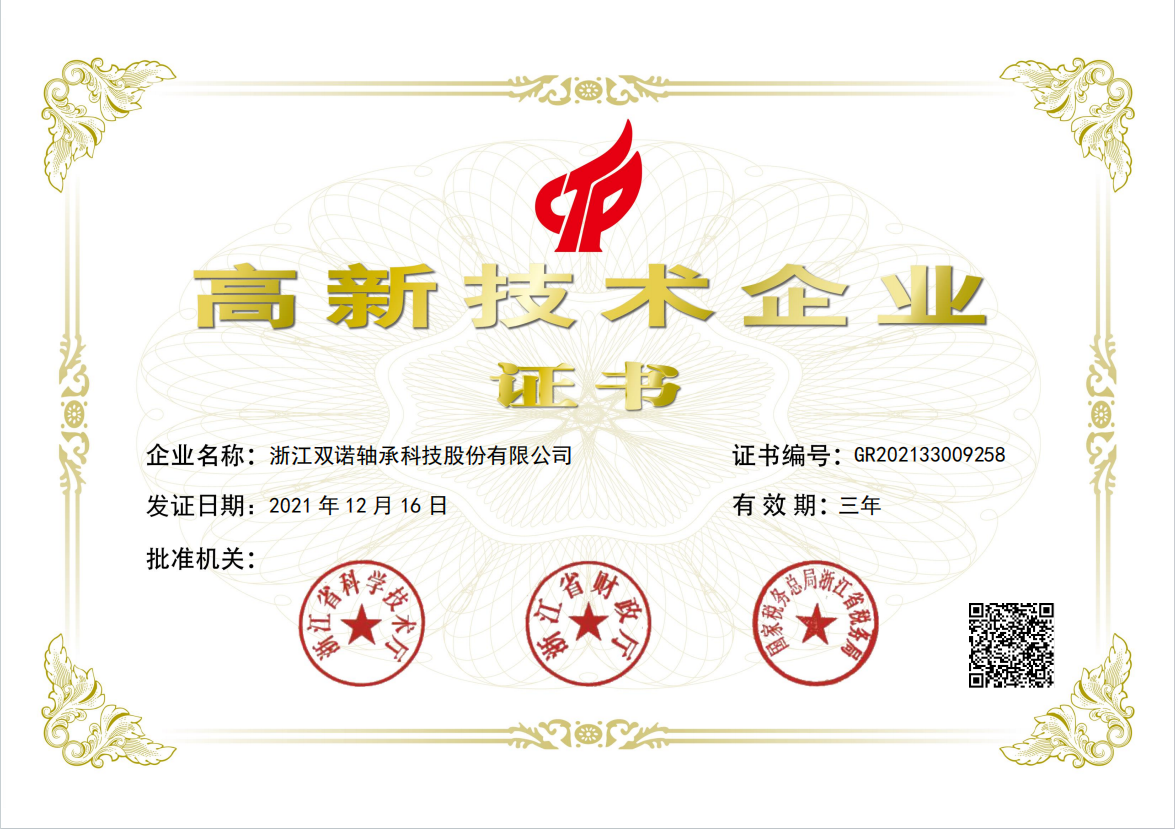
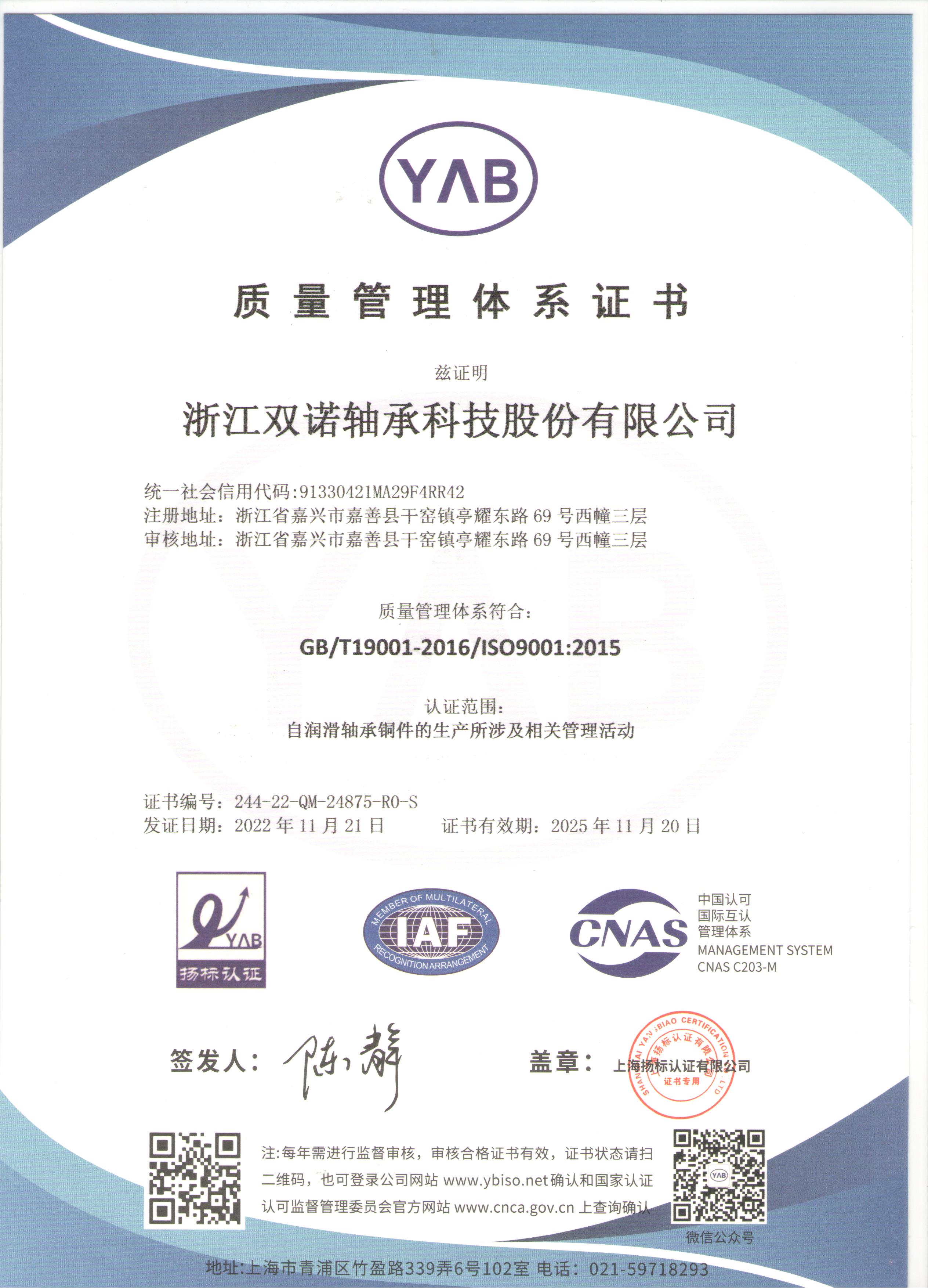
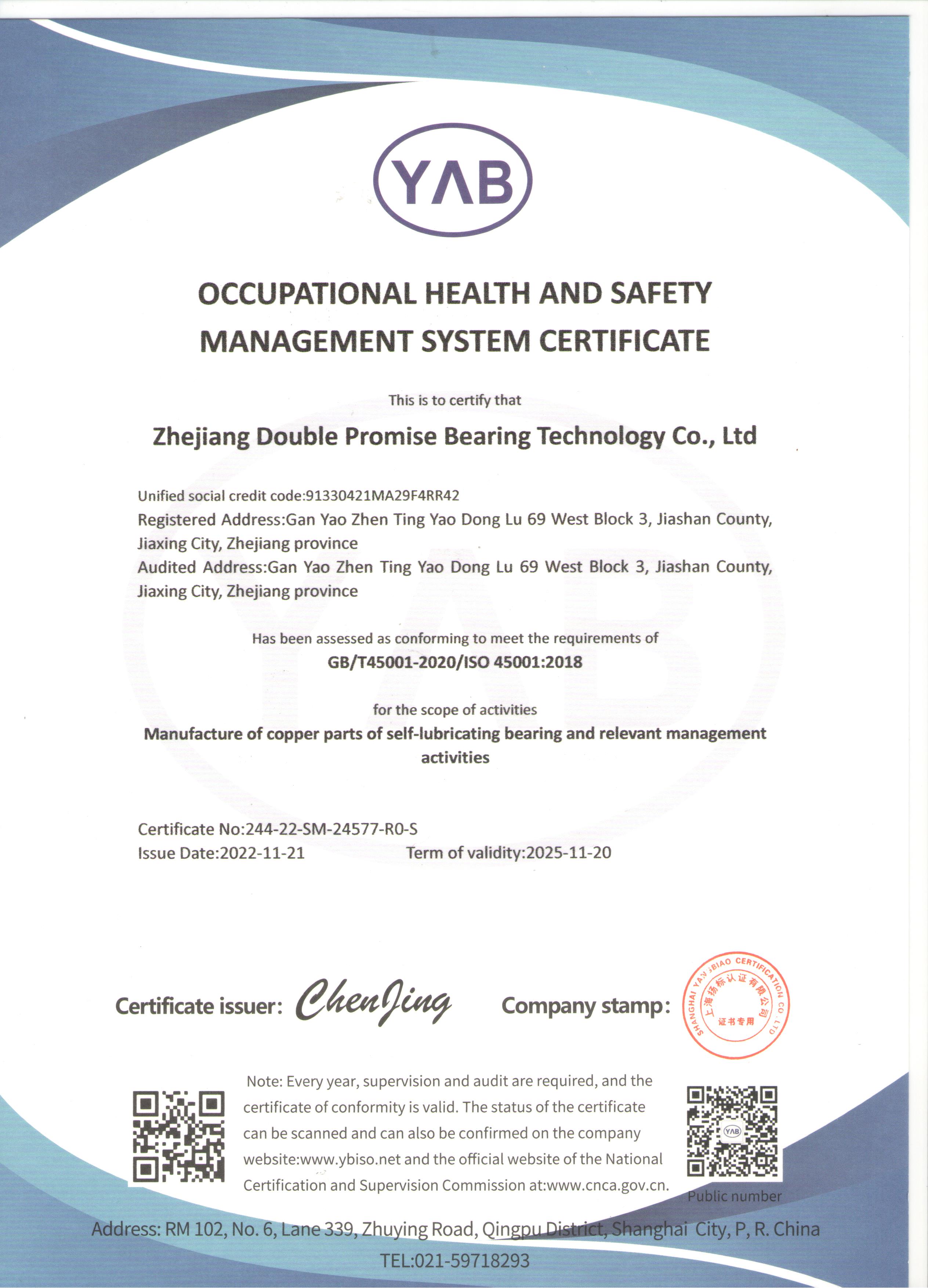
Vår ære //
ære.
Zhejiang Shuangnuo Bearing Technology Co., Ltd.
Streng kvalitetskontroll //
Fokuser på kvalitet når du velger produkter.
Fokuser på hver prosess for å lage produkter av høy kvalitet.
Vi er fullstendig klar over at kun ved å tilby produkter av høy kvalitet kan vi møte behovene til våre kunder og etablere et godt omdømme og troverdighet.

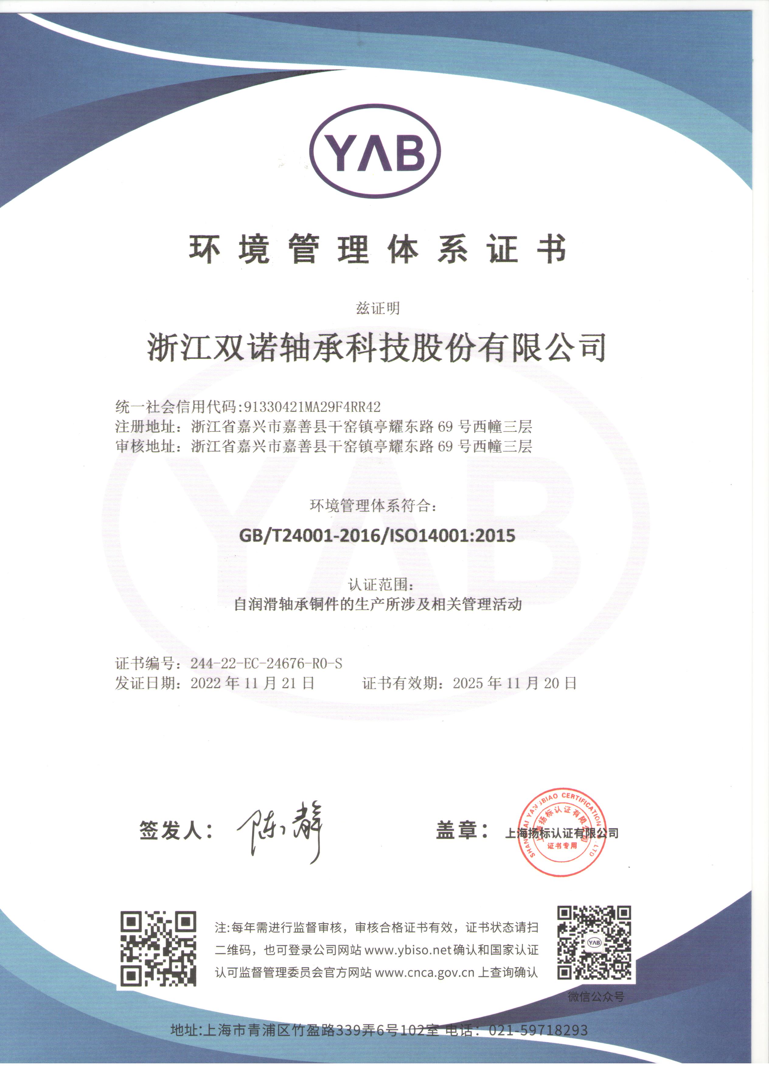
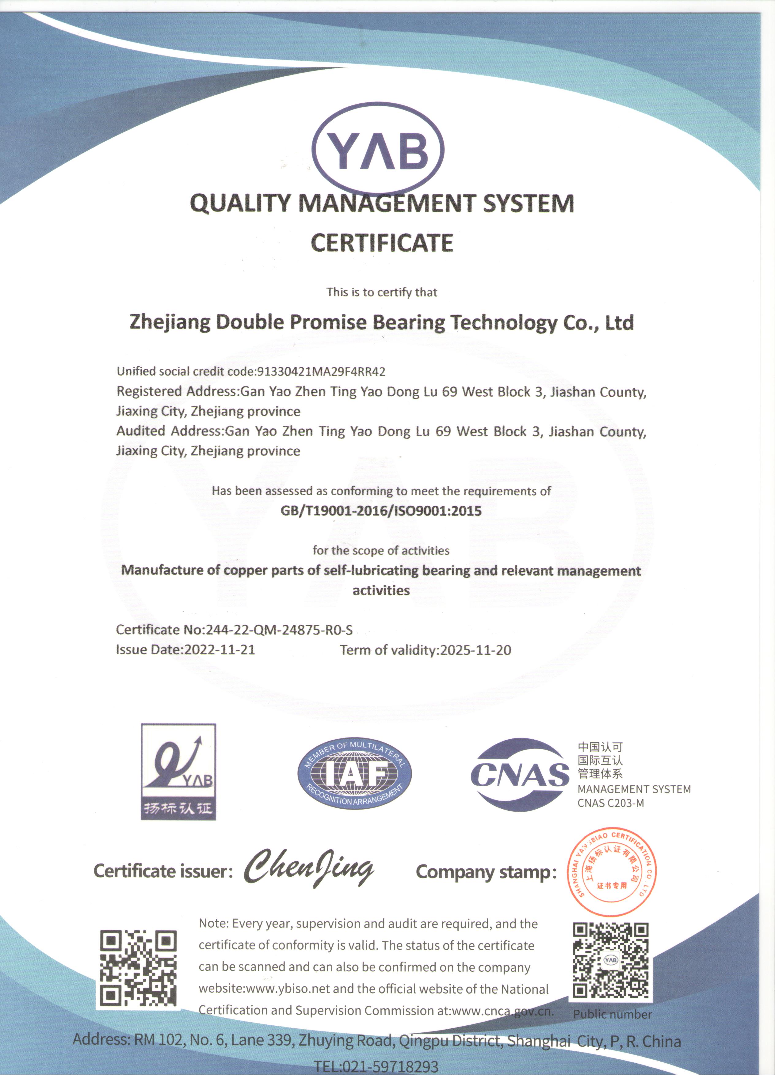
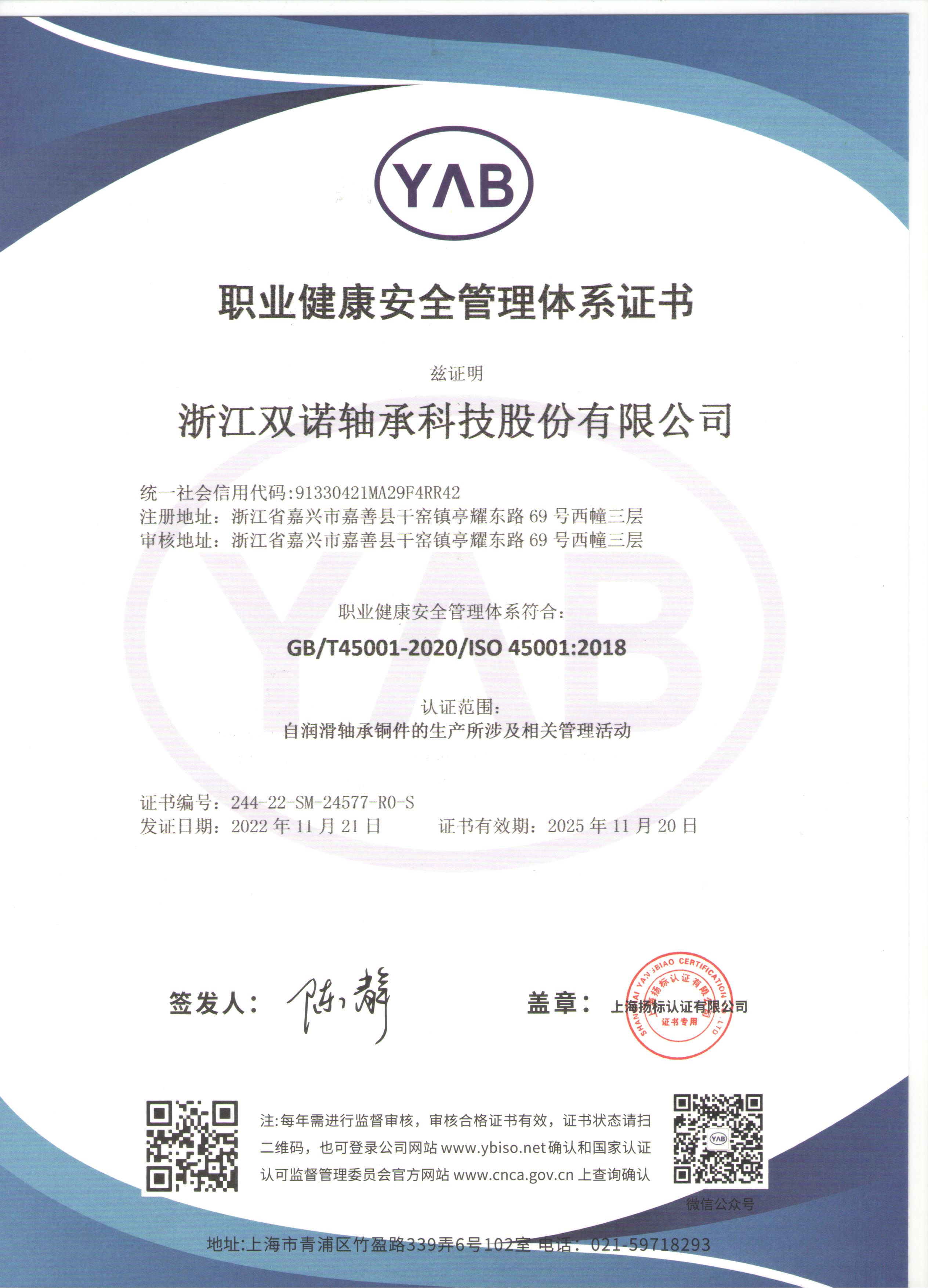
Vi krever at selvsmørende kobberlegeringsprodukter skal overholde relevante nasjonale standarder og forskrifter. Vi vil strengt overholde nasjonale kvalitetsinspeksjonsstandarder for å sikre at hvert produkt vi leverer oppfyller kvalitetskravene og gjennomgår nødvendige test- og sertifiseringsprosedyrer.